Friday, 7 December 2012

Raspberry Pi, the BerryClip and Java

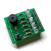
If you are looking to start exploring hardware interfacing with the Raspberry Pi, the BerryClip from http://www.raspberrypi-spy.co.uk provides an excellent starting point. For around £5 you get a kit containing 6 LEDS, a push button, Buzzer, printed circuit board and other required components to create the expansion board.

I ordered the board via Ebay and it came a few days later.  The board took less than an hour to assemble and a set of test scripts in python written by Matt Hawkins, the BerryClip's creator are available for download.

Carrying on from the Stepper Motor code that I have written using the Pi4J Library I decided to see if I could get the BerryClip working from Java. This seemed pretty straight forward apart from finding the that the Pi4J library GPIO names do not seem to align with those in python. I created a class to test each LED, once I had the correct GPIO names reference in my code the LEDs worked without any issues.

Pi4J to Berry Clip GPIO Names
FunctionPi4J GPIO Name
LED 1GPIO_14
LED 2GPIO_13
LED 3GPIO_12
LED 4GPIO_03
LED 5GPIO_00
LED 6GPIO_07
SwitchGPIO_11
BuzzerTBD

One of the example python scripts provided with the BerryClip is a Dice Simulator so I decided to see if I could create a similar function from Java. The resulting code is included below.

Dice.java
/**
 * 
 * Implementation of a D6 for the Berry Clip Raspberry Pi add on available from http://www.raspberrypi-spy.co.uk
 * 
 * Based on an example by Matt Hawkins
 * 
 */

package com.qubecad.pi.dice;

import com.pi4j.io.gpio.GpioController;
import com.pi4j.io.gpio.GpioFactory;
import com.pi4j.io.gpio.GpioPinDigitalInput;
import com.pi4j.io.gpio.GpioPinDigitalOutput;
import com.pi4j.io.gpio.PinPullResistance;
import com.pi4j.io.gpio.PinState;
import com.pi4j.io.gpio.RaspiPin;

public class Dice {

 public static void main(String[] args) throws InterruptedException {

  GpioController gpio = GpioFactory.getInstance();

  // Set up the pins and set low to start
  System.out.println("Setting up GPIO Pins for output");
  GpioPinDigitalOutput pina = gpio.provisionDigitalOuputPin(RaspiPin.GPIO_07, "Pin A", PinState.LOW);
  GpioPinDigitalOutput pinb = gpio.provisionDigitalOuputPin(RaspiPin.GPIO_00, "Pin B", PinState.LOW);
  GpioPinDigitalOutput pinc = gpio.provisionDigitalOuputPin(RaspiPin.GPIO_03, "Pin C", PinState.LOW);
  GpioPinDigitalOutput pind = gpio.provisionDigitalOuputPin(RaspiPin.GPIO_12, "Pin D", PinState.LOW);
  GpioPinDigitalOutput pine = gpio.provisionDigitalOuputPin(RaspiPin.GPIO_13, "Pin E", PinState.LOW);
  GpioPinDigitalOutput pinf = gpio.provisionDigitalOuputPin(RaspiPin.GPIO_14, "Pin F", PinState.LOW);

  // Setup pin for button

  GpioPinDigitalInput roleButton = gpio
    .provisionDigitalInputPin(RaspiPin.GPIO_11, "Role Button", PinPullResistance.PULL_DOWN);

  // add a listener for the button press event

  roleButton.addListener(new GpioRoleListener(pina, pinb, pinc, pind, pine, pinf));

  // start a loop until the user quits via CTRL C

  while (true) {
   Thread.sleep(500);

  }

 }

}


GpioRoleListener.java


/**
 * 
 * Implementation of a D6 for the Berry Clip Raspberry Pi add on available from http://www.raspberrypi-spy.co.uk
 * 
 * Based on an example by Matt Hawkins
 * 
 */


package com.qubecad.pi.dice;

import java.util.HashMap;
import java.util.Random;

import com.pi4j.io.gpio.GpioPinDigitalOutput;
import com.pi4j.io.gpio.event.GpioPinDigitalStateChangeEvent;
import com.pi4j.io.gpio.event.GpioPinListenerDigital;

class GpioRoleListener implements GpioPinListenerDigital {

 private static GpioPinDigitalOutput resultpina;
 private static GpioPinDigitalOutput resultpinb;
 private static GpioPinDigitalOutput resultpinc;
 private static GpioPinDigitalOutput resultpind;
 private static GpioPinDigitalOutput resultpine;
 private static GpioPinDigitalOutput resultpinf;

 private static HashMap diceresult = new HashMap();

 /**
  * Listener to handle the Button Press event and roll the dice
  *  
  */


 public GpioRoleListener(GpioPinDigitalOutput pina, GpioPinDigitalOutput pinb, GpioPinDigitalOutput pinc,
   GpioPinDigitalOutput pind, GpioPinDigitalOutput pine, GpioPinDigitalOutput pinf) {

  // pass through the output pins and setup the dice roll results

  resultpina = pina;
  resultpinb = pinb;
  resultpinc = pinc;
  resultpind = pind;
  resultpine = pine;
  resultpinf = pinf;

  diceresult.put(0, "000001");
  diceresult.put(1, "000011");
  diceresult.put(2, "000111");
  diceresult.put(3, "001111");
  diceresult.put(4, "011111");
  diceresult.put(5, "111111");

 }

 /** (non-Javadoc)
  * @see com.pi4j.io.gpio.event.GpioPinListenerDigital#handleGpioPinDigitalStateChangeEvent(com.pi4j.io.gpio.event.GpioPinDigitalStateChangeEvent)
  */
 @Override
 public void handleGpioPinDigitalStateChangeEvent(GpioPinDigitalStateChangeEvent event) {

  // check the button state, if HIGH roll the dice and set the LEDS

  if (event.getState().isHigh()) {
   Random seed = new Random();

   String result = (String) diceresult.get(seed.nextInt(6));
   System.out.println(result);

   setPin(resultpina, result.charAt(0));
   setPin(resultpinb, result.charAt(1));
   setPin(resultpinc, result.charAt(2));
   setPin(resultpind, result.charAt(3));
   setPin(resultpine, result.charAt(4));
   setPin(resultpinf, result.charAt(5));
  }

 }

 /**
  * 
  * Sets the passed pin Low or High depending on the passed value.
  * 
  * @param pin
  * @param value
  */
 private static void setPin(GpioPinDigitalOutput pin, char value) {
  if (value == '0') {

   pin.low();
  } else {

   pin.high();
  }
 }

}

The above code can be found in my Git Hub Repository at https://github.com/qubecad/Pi-BerryCLip
If you are looking to start using the GPIO on your Raspberry PI the BerryClip is an excellent starting point and well worth the low cost.

Further details of pi4j can be found at http://pi4j.com. The BerryClip as well as a wealth of tutorials and information can be found at http://www.raspberrypi-spy.co.uk
Thursday, 25 October 2012

RASPBERRY PI STEPPER MOTOR USING C# AND MONO.


With the aid of the libpigpio shared C library from David's blog and the mono runtime I spent a morning messing around my Pi and Stepper Motor running using c#. Using the libpiggio and the c# wrapper (also by David) it is makes controlling the GPIO pins for output easy. I found I had to compile the library on the pi, copying the provided .so file did not seem to work but the instructions are provided in the libpigpio.h file so it is not to much of an upheaval, you need to have gcc installed though. Once that was working and tested with one of the examples provided, I put together a class which lets me easily control the motor. The resulting code is shown below:


using System;
using LibPiGpio;
using System.Collections;
using System.Threading;

namespace ConsoleApplication1
{
    class Stepper
    {
        private int pina=0;
        private  int pinb=0;
        private  int pinc=0;
        private  int pind = 0;
        private  string[] graycode=new string[8]{"1000","1100","0100","0110","0010","0011","0001,","1001"};
        private string[] reversegraycode = new string[8] { "1001", "0001", "0011", "0010", "0110", "0100", "1100,", "1000" };
       public Stepper(int setpina, int setpinb, int setpinc, int setpind)
        {
            pina = setpina;
            pinb = setpinb;
            pinc = setpinc;
            pind = setpind;
            RpiGpio.SetOutputPins(new[] { setpina, setpinb, setpinc, setpind });
            RpiGpio.Pins[pina] = false;
            RpiGpio.Pins[pinb] = false;
            RpiGpio.Pins[pinc] = false;
            RpiGpio.Pins[pind] = false;


       }

        public void forward(int delay)
        {

            foreach (String value in graycode)
            {

                setPin(pina, value[0]);
                setPin(pinb, value[1]);
                setPin(pinc, value[2]);
                setPin(pind, value[3]);


                Thread.Sleep(delay);

            }
        }

        public void reverse(int delay)
        {
            foreach (String value in reversegraycode)
            {

                setPin(pina, value[0]);
                setPin(pinb, value[1]);
                setPin(pinc, value[2]);
                setPin(pind, value[3]);


                Thread.Sleep(delay);

            }
        }

        private void setPin(int pin, char value)
        {
            if (value == '0')
            {
                RpiGpio.Pins[pin] = false;

            }
            else
            {
                RpiGpio.Pins[pin] = true;

            }

        }


    }
}
The below code shows Stepper.cs in use.

using System;
using LibPiGpio;
using System.Threading;
using System.Collections;

namespace ConsoleApplication1
{
    class Program
    {
        static void Main(string[] args)
        {


            // setup the stepper motor and specify which GPIO pins to use.
            Stepper motor = new Stepper(24, 25, 8, 7);

            Console.WriteLine("Stepper Motor stepup complete");
            Console.WriteLine("Press up or Down Arrow keys to drive motor forwards or reverse.");
           
            // start checking for key presses
            ConsoleKeyInfo keyinfo;
            do
            {
                keyinfo = Console.ReadKey();
                

                if (keyinfo.Key.ToString()=="UpArrow"){
                    motor.forward(1);
                
                };

                if (keyinfo.Key.ToString() == "DownArrow")
                {
                    motor.reverse(1);

                };
            }
            while (keyinfo.Key != ConsoleKey.X);
         
        }
    
    
    }


}

The Visual Studio c# Project can be downloaded from https://github.com/qubecad/Csharp.git

Tuesday, 23 October 2012

Raspberry Pi Stepper Motor Control using Java.

I came across the Pi4J Project today. The project is working on a library to allow Pi programming from Java. It is not at version 1 yet so still quiet new but the library lets you access the GPIO port on your Pi and join in some of the fun I thought you needed to use python for.

My Pi is currently connected to a stepper motor so I thought I would have ago at getting it to run from java,the below code is the result. Once I had the pi setup and proved the java setup was working correctly I used Eclipse on my Windows PC to write my code/compile and WinSCP to transfer it to the Pi. 

The Pi4J project have a number of examples on their site and their control example (http://pi4j.com/example/control.html) was the starting point for my code. 

I am using a 28BYJ-48  stepper motor and ULN 2003 driver board which I picked up from ebay awhile ago.

Update: The latest version of Pi4J now includes a dedicated stepper motor class and example code.

The eclipse project can be download from: http://github.com/qubecad/hmm-pi.git


package com.qubecad.pi.stepper;

import java.util.HashMap;

import com.pi4j.io.gpio.GpioController;
import com.pi4j.io.gpio.GpioFactory;
import com.pi4j.io.gpio.GpioPinDigitalOutput;
import com.pi4j.io.gpio.PinState;
import com.pi4j.io.gpio.RaspiPin;

public class PiStepper {

 /**
  * 
  * Driving a Stepper Motor From Java 
  * 
  * @param args
  * @throws InterruptedException 
  */
 public static void main(String[] args) throws InterruptedException {


  // create gpio controller
  GpioController gpio = GpioFactory.getInstance();

  // Set up the pins and set low to start
  System.out.print("Setting up GPIO Pins for ouput");
  GpioPinDigitalOutput pina = gpio.provisionDigitalOuputPin(RaspiPin.GPIO_05, "Pin A", PinState.LOW);
  GpioPinDigitalOutput pinb = gpio.provisionDigitalOuputPin(RaspiPin.GPIO_06, "Pin B", PinState.LOW);
  GpioPinDigitalOutput pinc = gpio.provisionDigitalOuputPin(RaspiPin.GPIO_10, "Pin C", PinState.LOW);
  GpioPinDigitalOutput pind = gpio.provisionDigitalOuputPin(RaspiPin.GPIO_11, "Pin D", PinState.LOW);


  HashMap driveLogic=new HashMap();

  driveLogic.put(0, "1001");
  driveLogic.put(1, "0001");
  driveLogic.put(2, "0011");
  driveLogic.put(3, "0010");
  driveLogic.put(4, "0110");
  driveLogic.put(5, "0100");
  driveLogic.put(6, "1100");
  driveLogic.put(7, "1000");

  System.out.print("Driving motor");
  while (true) {
   for (int i = 1; i < driveLogic.size(); i++) {

    String grayCode = (String) driveLogic.get(i);
    setPin(pina,grayCode.charAt(0));
    setPin(pinb,grayCode.charAt(1));
    setPin(pinc,grayCode.charAt(2));
    setPin(pind,grayCode.charAt(3));

    Thread.sleep(10);
   }
  }

 }

 /**
  * 
  * Sets the passed pin Low or High depending on the passed value.
  * 
  * @param pin
  * @param value
  */
 private static void setPin(GpioPinDigitalOutput pin,char value){
  if (value == '0') {

   pin.low();
  } else {

   pin.high();
  }
 }

}

Using the Raspberry Pi remotely from a Windows PC.


Having a Raspberry pi and desktop/Laptop PC can lead to a desktop covered in keyboards and mice. To reduce this (and stop confusion over which mouse or keyboard you should be using)  you can access the pi remotely using putty and a X server. 

This guide assumes you have used the standard Raspbian image from (http://www.raspberrypi.org) which already has ssh configured. 


Install Putty (http://www.chiark.greenend.org.uk/~sgtatham/putty/

and 

Xming (http://sourceforge.net/projects/xming/) on your windows PC

Start Xming by launching XLaunch option from start menu 


Set the display settings to 'one window', if your select multiple each program you launch on your pi with run in it's own window. Make a note of the display number you will need this later.


Leave as default and press 'Next'.


  Leave as default and press 'Next'.


Save your configuration and press 'Finish'.


Start putty and configure a session to connect via ssh on port 22 using the ip address of your pi.


under connections/SSH/X11 tick the "Enable x11 forwarding" and set the X display location to
 localhost: (in this case 0 noted earlier).


Click on the session option and save your configuration.

Click open to connect to your Raspberry pi and log in. You now have a terminal access on your pi and use it as you would the LxTerminal.


Once logged in you can either start individual applications or a complete desktop session.

To use IDLE type idle

 or to start a full desktop session enter startlxde