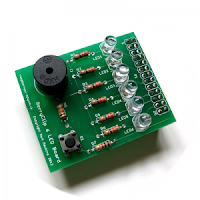
I ordered the board via Ebay and it came a few days later. The board took less than an hour to assemble and a set of test scripts in python written by Matt Hawkins, the BerryClip's creator are available for download.
Carrying on from the Stepper Motor code that I have written using the Pi4J Library I decided to see if I could get the BerryClip working from Java. This seemed pretty straight forward apart from finding the that the Pi4J library GPIO names do not seem to align with those in python. I created a class to test each LED, once I had the correct GPIO names reference in my code the LEDs worked without any issues.
| Function | Pi4J GPIO Name |
| LED 1 | GPIO_14 |
| LED 2 | GPIO_13 |
| LED 3 | GPIO_12 |
| LED 4 | GPIO_03 |
| LED 5 | GPIO_00 |
| LED 6 | GPIO_07 |
| Switch | GPIO_11 |
| Buzzer | TBD |
One of the example python scripts provided with the BerryClip is a Dice Simulator so I decided to see if I could create a similar function from Java. The resulting code is included below.
Dice.java
/**
 *
 * Implementation of a D6 for the Berry Clip Raspberry Pi add on available from http://www.raspberrypi-spy.co.uk
 *
 * Based on an example by Matt Hawkins
 *
 */

package com.qubecad.pi.dice;

import com.pi4j.io.gpio.GpioController;
import com.pi4j.io.gpio.GpioFactory;
import com.pi4j.io.gpio.GpioPinDigitalInput;
import com.pi4j.io.gpio.GpioPinDigitalOutput;
import com.pi4j.io.gpio.PinPullResistance;
import com.pi4j.io.gpio.PinState;
import com.pi4j.io.gpio.RaspiPin;

public class Dice {

 public static void main(String[] args) throws InterruptedException {

  GpioController gpio = GpioFactory.getInstance();

  // Set up the pins and set low to start
  System.out.println("Setting up GPIO Pins for output");
  GpioPinDigitalOutput pina = gpio.provisionDigitalOuputPin(RaspiPin.GPIO_07, "Pin A", PinState.LOW);
  GpioPinDigitalOutput pinb = gpio.provisionDigitalOuputPin(RaspiPin.GPIO_00, "Pin B", PinState.LOW);
  GpioPinDigitalOutput pinc = gpio.provisionDigitalOuputPin(RaspiPin.GPIO_03, "Pin C", PinState.LOW);
  GpioPinDigitalOutput pind = gpio.provisionDigitalOuputPin(RaspiPin.GPIO_12, "Pin D", PinState.LOW);
  GpioPinDigitalOutput pine = gpio.provisionDigitalOuputPin(RaspiPin.GPIO_13, "Pin E", PinState.LOW);
  GpioPinDigitalOutput pinf = gpio.provisionDigitalOuputPin(RaspiPin.GPIO_14, "Pin F", PinState.LOW);

  // Setup pin for button

  GpioPinDigitalInput roleButton = gpio
    .provisionDigitalInputPin(RaspiPin.GPIO_11, "Role Button", PinPullResistance.PULL_DOWN);

  // add a listener for the button press event

  roleButton.addListener(new GpioRoleListener(pina, pinb, pinc, pind, pine, pinf));

  // start a loop until the user quits via CTRL C

  while (true) {
   Thread.sleep(500);

  }

 }

}


GpioRoleListener.java


/**
 *
 * Implementation of a D6 for the Berry Clip Raspberry Pi add on available from http://www.raspberrypi-spy.co.uk
 *
 * Based on an example by Matt Hawkins
 *
 */


package com.qubecad.pi.dice;

import java.util.HashMap;
import java.util.Random;

import com.pi4j.io.gpio.GpioPinDigitalOutput;
import com.pi4j.io.gpio.event.GpioPinDigitalStateChangeEvent;
import com.pi4j.io.gpio.event.GpioPinListenerDigital;

class GpioRoleListener implements GpioPinListenerDigital {

 private static GpioPinDigitalOutput resultpina;
 private static GpioPinDigitalOutput resultpinb;
 private static GpioPinDigitalOutput resultpinc;
 private static GpioPinDigitalOutput resultpind;
 private static GpioPinDigitalOutput resultpine;
 private static GpioPinDigitalOutput resultpinf;

 private static HashMap diceresult = new HashMap();

 /**
  * Listener to handle the Button Press event and roll the dice
  *
  */


 public GpioRoleListener(GpioPinDigitalOutput pina, GpioPinDigitalOutput pinb, GpioPinDigitalOutput pinc,
   GpioPinDigitalOutput pind, GpioPinDigitalOutput pine, GpioPinDigitalOutput pinf) {

  // pass through the output pins and setup the dice roll results

  resultpina = pina;
  resultpinb = pinb;
  resultpinc = pinc;
  resultpind = pind;
  resultpine = pine;
  resultpinf = pinf;

  diceresult.put(0, "000001");
  diceresult.put(1, "000011");
  diceresult.put(2, "000111");
  diceresult.put(3, "001111");
  diceresult.put(4, "011111");
  diceresult.put(5, "111111");

 }

 /** (non-Javadoc)
  * @see com.pi4j.io.gpio.event.GpioPinListenerDigital#handleGpioPinDigitalStateChangeEvent(com.pi4j.io.gpio.event.GpioPinDigitalStateChangeEvent)
  */
 @Override
 public void handleGpioPinDigitalStateChangeEvent(GpioPinDigitalStateChangeEvent event) {

  // check the button state, if HIGH roll the dice and set the LEDS

  if (event.getState().isHigh()) {
   Random seed = new Random();

   String result = (String) diceresult.get(seed.nextInt(6));
   System.out.println(result);

   setPin(resultpina, result.charAt(0));
   setPin(resultpinb, result.charAt(1));
   setPin(resultpinc, result.charAt(2));
   setPin(resultpind, result.charAt(3));
   setPin(resultpine, result.charAt(4));
   setPin(resultpinf, result.charAt(5));
  }

 }

 /**
  *
  * Sets the passed pin Low or High depending on the passed value.
  *
  * @param pin
  * @param value
  */
 private static void setPin(GpioPinDigitalOutput pin, char value) {
  if (value == '0') {

   pin.low();
  } else {

   pin.high();
  }
 }

}
The above code can be found in my Git Hub Repository at https://github.com/qubecad/Pi-BerryCLip
If you are looking to start using the GPIO on your Raspberry PI the BerryClip is an excellent starting point and well worth the low cost.
Further details of pi4j can be found at http://pi4j.com. The BerryClip as well as a wealth of tutorials and information can be found at http://www.raspberrypi-spy.co.uk

1 comment:
Buzzer is to be found on GPIO_10
// Set up the buzz
GpioPinDigitalOutput buzzer = gpio.provisionDigitalOutputPin(RaspiPin.GPIO_10, "Buzzer", PinState.LOW);
Post a Comment